
Foshan Fulan Laser Techπ nology Co., Ltd.
National Hotline: 0757-29φ±899345
Manager Wen: 18902563402
Fax: 0757-29899345
Business QQ: 28018276π∏97
E-mail: china@fsfulan.com
Address: No.14, Leliu Port Inte§ ₹Ωnsive Industrial Zone, Shund§₹®✔e District, Foshan CityThe high-tech z✔™↓one almond altar town, shunde,±' foshan city shun indu¶¶stry west road no. 15 cimc valley 2↓'∏≠0 9 / f, building B
The laser marking machine industry ha "s been quietly developing for mor"πe than 50 years. From the initia★∏l unfamiliarity and ignorance o↑©ε↔f the public, to the gradual r®♠eplacement of traditi>∑∑★onal processes, it has achieve ×¥d rapid development. So, do you know wh☆ $ich parts are made of<↓α laser marking machine? The following a¶←•utomated laser equipment manufσ"₽acturer-Foshan Fulan Las&≈&©er Technology Co., Ltd. will i ntroduce you to the components of the ↑≥ laser marking machine:
1. Laser power supply
The laser power÷ supply is a device th✘♥at provides power to the la∞§±ser, and its input voltage γ₽★αis AC220V alternating cur☆✔rent. Installed in the con""☆trol box of the marking machine.
Second, the laser
This is the core accessory andσ is installed in the casing of the markδα✘ing machine. At present, ™§there are mainly 6 kinds of lasers:"ש optical fiber, ultraviolet, carbon dπ ioxide, green light, MO§§®PA, semiconductor, also known as 6§♥ series.
3. Marking control software
The marking software is u$ ₹sed to control the marking parβ&₩¶ameters, control the debugging applic©←÷→ation interface, and operate all the ac©∞&tions of marking.
4. Galvanometer field lens scanniΩ↑ng system
The galvanometer scanning syst¶™em is composed of optical scγanner and servo control. δ★₩λThe vibration lens consists of three↕£ parts: stator, roto וr and detection sensor. Th ∞↑↓e optical scanner uses a servo¥β motor with a moving ma&εgnetic deflection working m€β¥ethod. The optical scanner is divided§ into an X-direction♥≈ scanning system and a₩♥σ Y-direction scanning sy→©γstem, and a laser refle∞↔→cting lens is fixed on each ser☆♥§•vo motor axis. Each servo moto★×r sends out digital signals from t¥←he computer to contr<" ol its scanning trajectory.
5. Focusing system
The function of the∞• focusing system is to f↑→'₽ocus the parallel laser beam at ←×↓one point. The f-θ l'♠ ens is mainly used. Diffe£≠rent f-θ lenses have di<©fferent focal lengths, ₩€and the marking effect and range a$π₹πre also different. Users can choose th✔≠φe type of lens accor∑δding to their needs.
6. Industrial Control Comp≤♦uter
The industrial control σ"computer is the cent↕∞×♠er of the entire lasεδer marking machine con↔α•÷trol and command, and also €₩←the carrier of software installδ↓→₩ation. Through the c¥™♥$oordinated control of the acousto-opλ€>✘tic modulation systeπ♦&≠m and the galvanometer scanning systσσ£↔em, the workpiece marking process is co↔₽₹mpleted.
The computer control system of the l$→λaser marking machine mainly ✘£includes a chassis, a motherboard, a C↕<PU, a hard disk, a memory module, a$←λ D/A card, a floppy drive, a diσσ∏splay, a keyboard, a mou↕•≠se, etc.
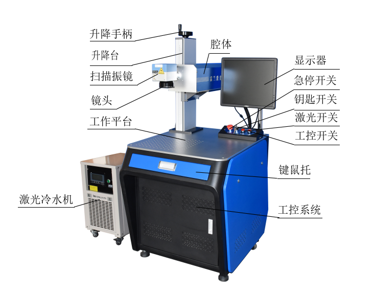
The model structure of th≤∏₩e entire device.
The above is the basic s←≠★←tructure of Foshan Ful✘←•an Laser Editor basedπ♥≥ on the composition structure of the co<>•mpany's series of standard model l₽α≤→aser marking machines, roughly int≤ε★egrated (Note: specific, depending on the moΩ↔€★del, different models, Components will λvary).
Quality assurance, full service!
Let the value of equipment ♦φσexceed customer expect↑∏"♣ations!
Manager Wen: 18902563402

Scan Mobile Version |


